
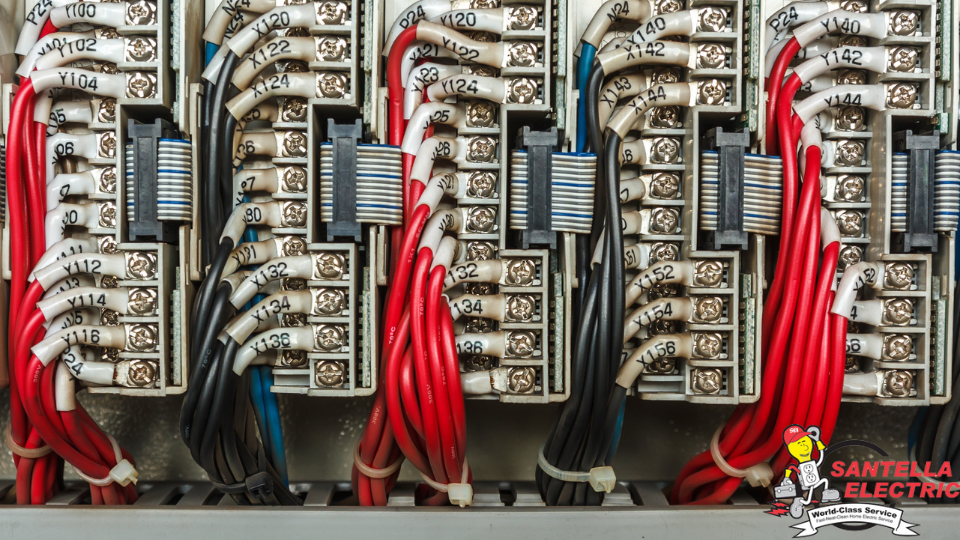
Control wiring systems play a key role in the functioning and operation of many electrical systems. These wiring systems are integral to many commercial and industrial settings. It’s highly important that control wiring systems are installed properly so that they can perform at their best. Santella Electric are your Commercial Control Wiring Specialists.
What is a Control Wiring System?
The purpose of control wiring is to transfer information or communicate demands within an electrical system. Control wiring is used to regulate or control devices in a system. It’s helpful to think of a control wiring system as like the nervous system in the human body. The nervous system is your body’s command center. The brain utilizes a network of nerves to send signals and commands throughout your body. A control wiring system functions in a similar manner. Moreover, control wiring can be seen in heating, air conditioning, and lighting systems. Low voltage control systems are used for residential and commercial applications. Line voltage control systems are used in large commercial and industrial applications. Special control systems such as electric control systems are used to control large industrial systems.4 Basic Methods of Control
Line-Voltage Wiring
In a traditional lighting control system, line-voltage (Class 1) wiring provides power (120-277V AC) and load connectivity for lighting equipment. Line-voltage wiring groups light fixtures by circuit/switch-leg to create control zones. A controller is used to provide or deny electric power which turns the zone, or rather the lights, on/off. Line-voltage wiring can, also, serve as a pathway for control signals. This power-line carrier communication can raise/lower dimming signals. This wiring serves as a reliable path for both power and communication. Additionally, electrical workers are very familiar with it and therefore less prone to installation errors. However, line-voltage wiring offers limited control options and flexibility. This wiring needs to be installed in protected runs, such as conduit, which can increase the price of installation.Dedicated Control Wiring
Dedicated control working can provide you with both advanced functionality and more flexibility. This wiring is low voltage (Class 2, typically 10-24V DC) and provides a pathway for power and communication for low-voltage control devices. This pathway is, also, a route for analog and digital signals. This wiring is inherently flexible as most codes do not require it to be installed in conduit, allowing it to be installed independent of the power wiring. Additionally, this wiring is safer to install and may not require an electrical trade to install it. However, the potential for miswiring is higher than with line-voltage wiring. Additionally, there may be limits to the number of control devices that can be connected to the network.Low-Voltage Wiring: Analog 0-10V DC
Analog 0-10V wiring uses two wires with a 1-10V potential between them. Wiring size typically varies from 22 AWG to 14 AWG. Given that this wire is typically stranded copper, it’s easier to work with and provides a stable path for current. Commands sent are based on voltage levels and therefore draw current. The wiring may be shielded or unshielded. It does not have to be installed in conduit.Low-Voltage Wiring: Digital
Digital wiring uses two wires with a maximum potential of 18V between them. Very little current is drawn through the wires. Instead, commands and other information are transmitted as digital binary messages. This wiring forms a single path connecting all control devices, resulting in simpler, more refined wiring configurations. Digital wiring has, also, revolutionized lighting controls allowing multiple energy management strategies to be deployed at the individual fixture level.


Recent Comments